YENA Offroad Limited Anti-theft Bracket Assembly

Please read in full and watch the installation video on our web site under the Assembly tab before installation.
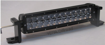
Step 1) Attach load bearing bracket (load bracket) to light bar using the two stainless steel bolts provided with each bracket Note: Do not use original bolts as they might be too long. Tighten both bolts securely using a 6mm allen wrench or hex key T handle to properly align the brackets with the light bar (adjustment of the light bar to the horizon is done in final step).
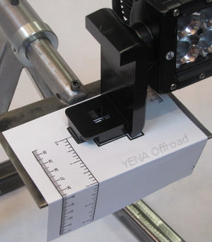
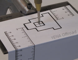
Step 2) Place the light bar on the mounting surface in the desired location. Slide the mounting templates under the load brackets at both ends of the light bar. Align both brackets with the bracket outlines on the mounting templates.
Step 3) Use the ruler guides on mounting templates to help assure light is aligned properly to the mounting surface edge before drilling mounting holes. Use tape to secure mounting templates to mounting surface. Important: Check that both load brackets are aligned with the bracket outlines on both mounting templates and the distance from the edge of the mounting surface is consistent on both ruler guides before drilling holes.
Step 4) Center punch the middle of both crosses within bracket outlines. Drill the first of two pilot holes using a 1/8” or smaller drill bit. Using a 3/16” drill bit to enlarge both pilot holes. Using at least a 9/16” or 5/8” (recommended) drill bit to enlarge both holes to accept standard ½” carriage head bolts or our patented Anti-theft Bolts. Important: It is very important to drill two separate smaller pilot holes so the final large drill bit does not “walk off” center as it is being used.
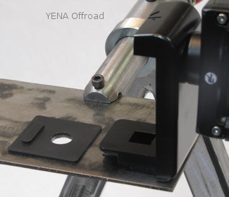
Step 5) Remove the mounting templates and place the black mounting pad with the raised tab facing up and furthermost away from the light bar. Place light bar onto the mounting pads and align the holes in the load brackets, pads and the newly drilled mounting holes. Insert the ½” stainless steel carriage bolt into the load bracket making sure the square shank of the bolt drops into the machined square hole.
Step 6) Install the stainless steel ½” flat washer, ½” lock washer , and ½” nut on both mounting bolts. Only install ½” nuts with a few turns. Important: The ½” nuts must be left loose so the load brackets can be lifted up off the mounting surface to install interlocking security brackets in Step 7.
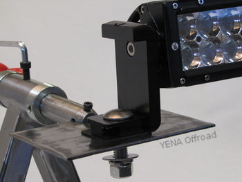
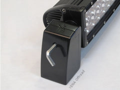
Step 7) Lift up the light bar to slide the security bracket underneath the load bracket. Align the raised tab facing up (Step 5) with the slot in the base of the security bracket. Then lower light bar to couple both brackets together. Repeat process with the other bracket set at the opposite end of the light bar before tightening either of the two ½” nuts.
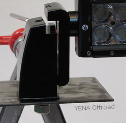
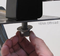
Step 8) Grab the threads of the carriage bolt and turn back and forth to ensure the square shank of the blot is still in the square hole of the load bracket. After checking bolt is in place apply a slight downward force on ½”nut to keep the bolt in place as the nut is screwed on. Tighten until finger tight and then repeat on second mounting bolt at the opposite end of the light bar.
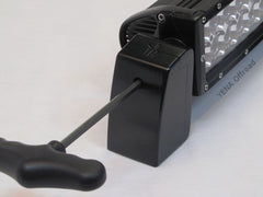
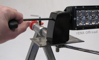
Step 9) Insert a hex key T handle or screw driver through the hole in the security bracket to prevent the bracket turning when tightening the ½” nut. Tighten both ½” nuts until lock washers are compressed flat. Important: The bracket must be held in place as tightening the ½” nuts will exert a rotational force on the brackets. This could affect the alignment of the brackets to the light bar, and/or place stress on the end cap of the light bar. If pliers are used to hold the bracket, be sure protect the surface finish on both sides of the bracket from jaws of the pliers.
Step 10) ) Insert the hex key T handle or allen wrench through the hole in the security bracket and loosen the bolts securing the light bar to the load brackets. Adjust the light bar to the desired angle and retighten both bolts. Note: The security bracket allows access to the bolts to adjust the light bar but stops their removal.