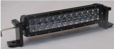
YENA Offroad Limited Anti-theft Bolt Assembly
Follow the next 14 steps to assemble the Stainless Steel Anti-theft Bolt (Patented). Please see the about us page for our first order details.
Please read in full and watch the installation video on our web site under the Assembly tab before installation.
Step 1) Attach load bearing bracket (load bracket) to light bar using the two stainless steel bolts provided with each bracket Note: Do not use original bolts as they might be too long. Tighten both bolts securely using a 6mm allen wrench or hex key T handle to properly align the brackets with the light bar (adjustment of the light bar to the horizon is done in final step).
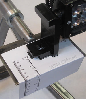
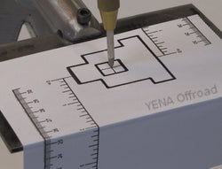
Step 2) Place the light bar on the mounting surface in the desired location. Slide the mounting templates under the load brackets at both ends of the light bar. Align both brackets with the bracket outlines on the mounting templates.
Step 3) Use the ruler guides on mounting templates to help assure light is aligned properly to the mounting surface edge before drilling mounting holes. Use tape to secure mounting templates to mounting surface. Important: Check that both load brackets are aligned with the bracket outlines on both mounting templates and the distance from the edge of the mounting surface is consistent on both ruler guides before drilling holes.
Step 4) Center punch the middle of both crosses within bracket outlines. Drill the first of two pilot holes using a 1/8” or smaller drill bit. Using a 3/16” drill bit to enlarge both pilot holes. Using at least a 9/16” or 5/8” (recommended) drill bit to enlarge both holes to accept standard ½” carriage head bolts or our patented Anti-theft Bolts. Important: It is very important to drill two separate smaller pilot holes so the final large drill bit does not “walk off” center as it is being used.
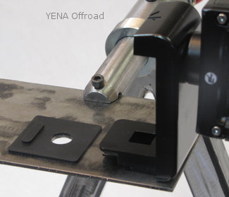
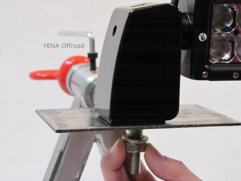
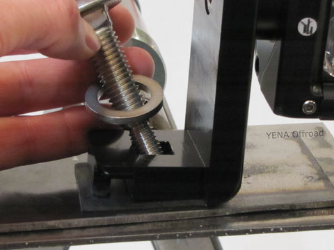
Step 5) Remove the mounting templates and place the black mounting pad with the raised tab facing up and furthermost away from the light bar. Place light bar onto the mounting pads and align the holes in the load brackets, pads and the newly drilled mounting holes. Insert the ½” anti-theft stainless steel bolt into the load bracket making sure the square shank of the bolt drops into the machined square hole.
Step 6) Install the stainless steel ½” flat washer, ½” lock washer , and the ½” low profile nut on both anti-theft mounting bolts. Only install ½” nuts with a few turns. Important: The ½” nuts must be left loose so the load brackets can be lifted up off the mounting surface to install interlocking security brackets in Step 7.
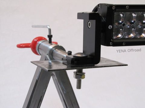
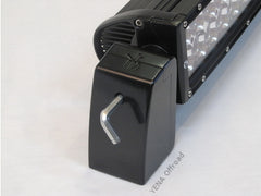
Step 7) Lift up the light bar to slide the security bracket underneath the load bracket. Align the raised tab facing up (Step 5) with the slot in the base of the security bracket. Then lower light bar to couple both brackets together. Repeat process with the other bracket set at the opposite end of the light bar before tightening either of the two ½” nuts.
Step 8) Grab the threads of the anti-theft bolt and turn back and forth to ensure the square shank of the blot is still in the square hole of the load bracket. After checking bolt is in place apply a slight downward force on ½”nut to keep the bolt in place as the nut is screwed on. Tighten until finger tight and then repeat on second mounting bolt at the opposite end of the light bar.
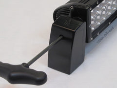
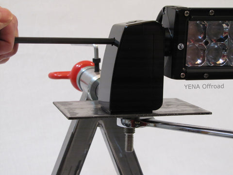
Step 9) Insert a hex key T handle or screw driver through the hole in the security bracket to prevent the bracket turning when tightening the ½” nut. Tighten both ½” nuts until lock washers are compressed flat. Important: The bracket must be held in place as tightening the ½” nuts will exert a rotational force on the brackets. This could affect the alignment of the brackets to the light bar, and/or place stress on the end cap of the light bar. If pliers are used to hold the bracket, be sure to protect the surface finish on both sides of the bracket from the jaws of the pliers.
VERY IMPOTANT NOTE: Due to various thicknesses of mounting surfaces the anti-theft bolts are ordered in different lengths for the each application. The Ant- theft bolts use two internal tooth washers and two 3/8” lock nuts provided for final installation of the protective sleeve. Also provided is an internal tooth washer and a standard 3/8” nut used for TRIAL ASSEMBLY of the protective sleeve (Step 10). DO NOT USE the two lock nuts until Step 12 after confirming the protective sleeve can be installed correctly as thread damage could result.
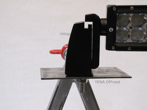
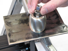
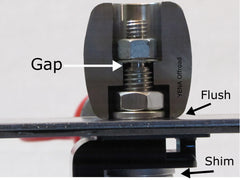
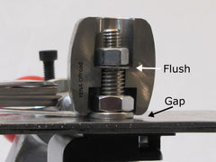
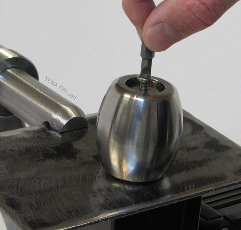
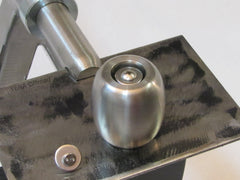
Step 10) For most installations the anti-theft bolts ordered will allow for proper installation of the protective sleeve. If the protective sleeve does not seat on the mounting surface then shims are also provided for adjusting the length of the anti-theft bolt. This Step 10 is to check that the protective sleeve can be installed properly by seating on the mounting surface so it does not rattle and stops access to the bolt so it cannot be cut off. Place the stainless steel protective sleeve onto the anti-theft bolt and install internal tooth washer and the STANDARD 3/8” nut. Tighten standard nut finger tight and confirm protective sleeve is flush with mounting surface and does not rattle. If protective sleeve does not sit flush and rattles go to Step 11 on how to shim anti-theft bolt. If protective sleeve sits flush then GRADUALLY tighten nut as you rotate protective sleeve clockwise until you can feel the protective sleeve has enough friction applied to stop it rotating freely, but still turns. Important: DO NOT overtighten nut as to prevent the protective sleeve from turning. Repeat this step for the second anti-theft bolt and protective sleeve before lock nuts are used. If trial fit of BOTH protective sleeves is successful then go to Step 12).
Step 11) After completing Step 10 and it is found the protective sleeve rattles then the provided shims must be installed between the head of the anti-theft bolt and the load bracket as follows. Remove the ½” nuts securing both anti-theft bolts. Important: The bracket must be held in place as loosening the ½” nuts will exert a rotational force on the brackets and place a stress on the end cap of the light bar. Lift the light bar up and remove each security bracket individually so as not to drop one. Remove anti-theft bolt, slide shim over bolt and re-insert into load bracket making sure the square shank of the bolt drops into the machined square hole as in Step 5. Repeat Steps 6 through 10. Note: Below is a visual reference for purpose of shim.
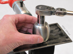
Step 12) After confirming correct installation for both protective sleeves in Step 10 remove standard 3/8” nut and internal tooth washer. Replace with unused internal tooth washer and 3/8” lock nuts provided. Tighten lock nut until protective sleeve is almost flush with mounting surface. When protective sleeve is sitting almost flush GRADUALLY tighten lock nut as you rotate protective sleeve until you can feel the protective sleeve has enough friction applied to stop it rotating freely, but still turns. Important: DO NOT overtighten lock nut as to prevent the protective sleeve from turning. Repeat procedure for the second anti-theft bolt and protective sleeve.
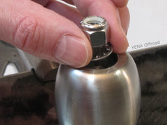

Step 13) With the protective sleeves installed they should rotate but the 3/8” lock nut will hold in place without loosening. Install the oversized washer and the tamper proof machine screw. This oversize washer prevents access to the lock nut. For additional security cover access to the oversized washer and tamper proof machine screw with a hardening compound like JB Weld. If access to the tamper proof screw and protective sleeve is easily accessible and a more permanent method of security is needed then the tamper proof cap can be used instead. Install the oversized washer and standard machine screw. Align tamper proof cap and gently tap into place until only dome of cap is showing. Repeat procedure for the second anti-theft bolt and protective sleeve.
Step 14) ) Insert the hex key T handle or allen wrench through the hole in the security bracket and loosen the bolts securing the light bar to the load brackets. Adjust the light bar to the desired angle and retighten both bolts. Note: The security bracket allows access to the bolts to adjust the light bar but stops their removal.